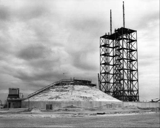

The blockhouse at LC-34, with the service structure rising behind it, November 1960.
At Marshall Space Flight Center the development of ground support equipment proceeded under a new office. With the reorganization of ABMA, on the takeover by NASA in March 1960, the Systems Support Equipment Laboratory disappeared. Most of the laboratory's personnel joined LOD as members of Theodor Poppel's Launch Facilities and Support Equipment Office (LFSEO). Poppel's experience with ground support equipment dated back to World War II. A native of Westphalia, Poppel had begun work at Peenemunde in 1940, following graduation from an engineering school in Frankenhausen. He had been among the first Germans to enter the United States in 1945. The deputy to Poppel, Lester Owens, like many American members of the von Braun team, was Alabama-born and Auburn-trained. Five of the six suboffices worked in Huntsville; the other line unit, R. P. Dodd's Launch Facilities Design Group, was based at the Cape.24
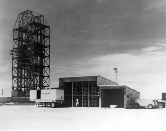
The high-pressure-gas facility.
By May 1960, LFSEO leaders felt sufficiently confident about the development of ground support equipment to discuss responsibilities for installing equipment at LC-34. A conference on the 17th set beneficial occupancy dates (the dates on which each facility within the complex would become available to MSFC and its contractors for installation of collateral equipment). MSFC plans called for a rudimentary high-pressure-gas (nitrogen and helium) facility. Two flatbed trailers, each with a 3,785-liter storage tank, pump, vaporizer, and associated equipment, would bring liquid nitrogen to the pad. After being routed through a vaporizer and warmed to 294 kelvins (21 degrees C), the gaseous nitrogen would be stored under high pressure in a cluster of bottles protected by a concrete vault. Two booster compressors located in the storage area would pressurize the helium. Since the introduction of upper stages after the third launch would increase high-pressure-gas requirements, Chester Wasileski's Propellants Service Design Group was planning a central compressor-converter for LC-37. The basic LC-34 arrangement, however, would be ready by 1 August 1960.
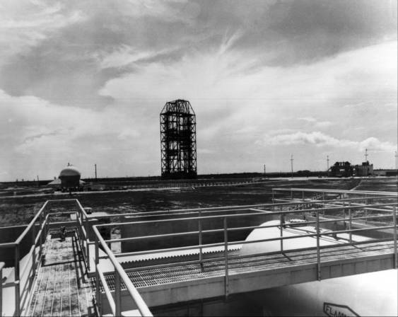
LOX facility (L), service structure (C), and pad (R), seen from the top of the RP-1 facility.
Discussion moved next to RP-1 facilities. LFSEO planned to test the integrated fuel storage and transfer system at Huntsville before 10 August. During the fall, the General Steel Tank Company would install the two 113,550-liter storage tanks at the pad. Hayes Aircraft personnel would then clean, install, assemble, and pressure-test the entire transfer system from tank to fuel mast. The two 3,785-liter-per-minute pumps were standard equipment and posed no problems. The propellant operations and status panel required additional testing at Huntsville, but would be ready for blockhouse installation in the fall. Wasileski thought the entire system could be operational by 1 February 1961.
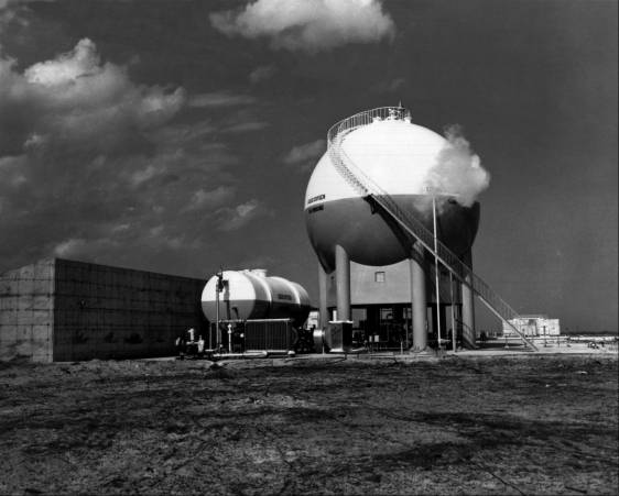
The LOX facility. The pad is to the left.
Wasileski envisioned a similar schedule for LOX facilities: completion of testing at Huntsville on 10 August; installation of storage and replenishing tanks by Chicago Bridge Company between September 1960 and 15 January 1961; cleaning, assembling, and installing the transfer system (the pipes that carried LOX from the tanks to the Saturn) by Hayes before 15 January 1961; and operational status as of 1 February 1961. During the installation, the Chicago Bridge Company would conduct a flow test between the storage tank and replenishing tank to qualify the vaporizer design.
Work on the cable masts was proceeding satisfactorily. The Saturn booster required a 21-meter aluminum boom to service the instrument compartment with pneumatic pressure, electrical power, and coolants. LFSEO expected to deliver the long mast 1 March 1961. Shorter cable masts, mounted on the launcher support arms, would provide pneumatic and electrical connections to the tail section of the booster. The electrical connections powered and monitored the propulsion system, while the pneumatic lines purged and pressurized the fuel systems. The conference set 1 February 1961 as the installation date for launcher support arms, hold-down arms, and short cable masts.25
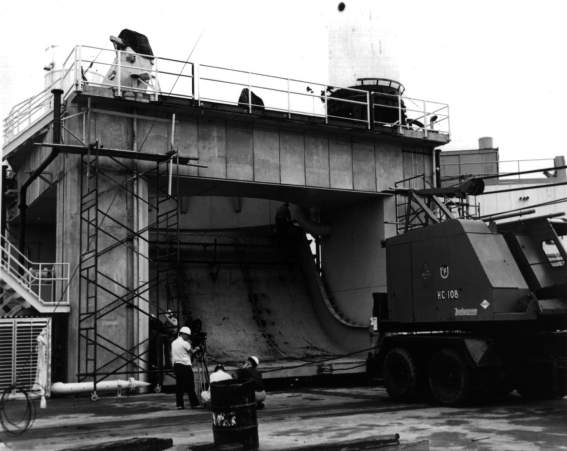
The flame deflector in position beneath the launch pad.
Development of the flame deflectors took Poppel's office about six months longer than expected. LFSEO had begun testing angles of impingement in early 1960 to establish the flow pattern for the Saturn's exhaust. If the deflector was set at the wrong angle, a detached shock wave would form, choke the exhaust flow, and raise the heat and pressure on the launch vehicle beyond tolerable limits. Donald Buchanan's Launcher System and Umbilical Tower Design Section experimented with several angles before contracting with the Hayes Corporation of Birmingham to construct two 80 degree deflectors. Delivery was set for November 1960, During subsequent tests in August 1960, Buchanan and Edwin Davis determined that a 60 degree deflector (30 degree angle of impingement) would further reduce the backflow. Although the 80 degree deflector still met launch vehicle requirements, rocket designers prevailed upon von Braun to modify the Hayes contract. The Birmingham firm shipped the first deflector to the Cape in April 1961. Due to its size, 6 x 8 x 13 meters, and weight, 99 tons, the deflector was shipped in seven sections.26
The change in the deflector design was not a unique event. The office frequently altered its designs to fit requirements of other MSFC groups; few concessions were made to LFSEO. For one example, the support arms could have been simplified by strengthening the booster frame. This LFSEO recommendation was rejected because it meant adding 1,100 kilograms to the launch vehicle weight. Eventually, the weight increased several times that amount, but for other reasons. MSFC officials, fearful of a rocket collision, restricted the size of the umbilical tower. An LFSEO engineer, believing the final design of the tower base was unsatisfactory, surreptitiously increased its dimensions. Speculation about German-American friction at Huntsville was largely unfounded, but disagreements between vehicle designers and ground support engineers were common.
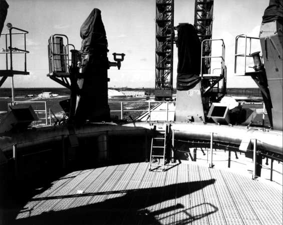
The top of the pedestal. The metal grating, a work platform, was removed before launch. The spray nozzles can be seen beneath the torus ring. The rocket rested on the hold-down arms, which are under protective covers. The rectangular ducts, (one of which is in front of the workman) removed exhaust gases.
By mid-1960, costs of the two Saturn launch facilities were burgeoning. A July Saturn Project Office memorandum noted that "rising costs, the influence of the committee on Saturn blast potential [Charles J. Hall Committee], and the full impact of [the Saturn] C-2 on the VHF-37 complex... indicated that approximately 44 millions were required in lieu of the available 31 millions [for FY 1961]."27 The Launch Operations Directorate established priorities to complete the essential portions of LC-34 and LC-37 while the remaining facilities awaited adequate funding: first, prepare LC-34 for the three Saturn booster shots without hydrogen capability or umbilical tower; second, prepare LC-37 as a backup pad for the second launch; third, complete LC-37 for launch of a two- or three-stage Saturn C-1 or C-2; fourth, complete LC-34 for Saturn C-1 configuration.* Construction of LC-34's umbilical tower began in September 1960 but stopped at the 8.2-meter level; the long cable mast would provide umbilical connections for the booster launches.28
24. MSFC, C-1, C-2 Comparison, pp. 100-102; Poppel interview, 12 Feb. 1973.
27. C. C. Parker, Chief, Ops. Off., MSFC, "Saturn FY-61 LOD Budget," 29 July 1960, encl.3.
28. Debus, memo, "Priority of Effort on Saturn Launch Facilities," 8 July 1960.


